Introduction
Measurement sources used for measuring fiber optic attenuation vary enormously in cost and performance. This application note explains what it is all about.
The range
| Inexpensive |
Surface emitting LED sources are used for testing multimode fiber. They emit a low power level with good power stability; however, their spectral characteristics are very poor. LED sources used for certification may require special spectral and beam geometry characteristics to ensure consistent measurement results. |
| Moderate |
Fabry-Perot laser sources are used for general single mode attenuation measuring. Lasers provide much better spectral accuracy than LEDs, and much higher power output. However, they tend to have problems with power stability.
If a broader spectral output is required for single mode measuring, edge emitting LEDs are available, however their power output tends to be excessively temperature sensitive. |
| Expensive |
Laser sources can be enhanced in various ways. The most common enhancements are:
- Fabry-Perot of DFB laser with tighter initial wavelength accuracy.
- Better wavelength stability using a Bragg grating and / or temperature control via a Peltier device.
- Wavelength tuning capability. A wide range of cost and performance is available for various specialist applications.
- Extra power stabilising techniques.
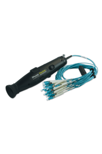
- Multiple lasers connected to a single connector port, which results in faster operation.
|
Center wavelength accuracy
The peak emitted wavelength of any source is usually called the center wavelength. In Fabry-Perot laser sources used for attenuation testing, the initial tolerance is typically ± 30 nm, which affects both attenuation effects, and measurement accuracy. In addition to this tolerance, temperature sensitivity of around 0.4 nm / °C creates further variation. The temperature effect can be virtually eliminated by use of temperature-controlled emitters.
To put all this in perspective: The effect of 0 - 40 °C temperature induced wavelength change will alter the attenuation dB measurement of a 50 Km single mode link by typically ± 0.25 dB. However, the link attenuation uncertainty caused by an initial tolerance of ± 30 nm would be about ± 0.95 dB. Note that the wavelength uncertainty of operational systems may be of a similar amount, in which case there may be some mismatch between the measured attenuation, and the attenuation seem by the operational system.
It is possible to select devices with better initial tolerances (e.g. for measurement purposes), however this has little practical benefit if the wavelength of installed systems also has a large uncertainty. As a practical compromise, a laser center wavelength tolerance of ± 20 nm is often specified for sources.
Course WDM lasers usually have a wavelength tolerance of about 3 nm, and DWDM lasers have a much tighter tolerance still. However, these DFB type lasers are not so ideal for measurement purposes, since coherent interference noise in cables tends to produce more measurement uncertainty. When DFB lasers are used, it is preferable to ensure a low reflection environment.
Spectral width
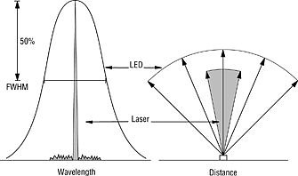
Sources emit light over a range of wavelengths. The spectral width may be specified in terms of FWHM, or Full Width Half Maximum. This is OK for transmission systems, but in measurement situations, there may be enough power outside this specification to affect attenuation measurements.
For example, an LED emits over a broad spectrum of 30 - 200 nm, depending on the type. This broad spectral width tends to overwhelm the issue of initial center wavelength tolerance.
If spectral width, initial tolerance, and temperature effects are included, a 1300 nm LED could be emitting some light anywhere over 1150 - 1450 nm. The 850 nm LED spectral width is generally around 50 nm FWHM.
Lasers have a much narrower spectrum of up to 5 nm FWHM, depending on the type. Therefore, for loss testing purposes, the laser center wavelength tolerance is more important, and the spectral width can generally be ignored.
Temperature changes do not significantly affect spectral width; however, temperature changes can cause sudden changes to laser operating modes. These sudden changes can cause fluctuations in output power, attenuation, and meter performance.
Power stability
The output power stability of sources is a significant issue:
- The output power of an LED source tends to vary with temperature. Depending on the type, variations of around 1 dB are possible for a surface emitting LED. Edge emitting LEDS can be highly unstable, and variations of up to 10 dB are possible.
- Fiber Coupled LED sources are much more stable than cheaper solutions which use a receptacle LED.
- A laser system is theoretically insensitive to temperature, since the laser circuit incorporates a back-facet monitor and feedback circuit to keep the laser output constant under all conditions. However, there are still variations caused by varying coupling efficiency between the laser and fiber. Variations more than 1 dB are possible.
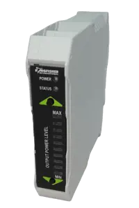
- As a result of temperature dependence, most sources have a significant warm up period and drift, both of which are annoying to users. Because of the variability of thermal stability between one emitter and another in production, sources often have vague power stability specifications: they tend to quote only typical values over a limited set of conditions. Obviously, these values may not be achieved. Kingfisher’s Ultra-Stable sources eliminate this problem, and quote maximum specifications, with no warmup period.
- Most laser sources are sensitive to back reflection. Back reflected light hits the power control detector (back facet monitor), so to compensate, the power control circuit reduces the laser power. We have found typical variability of around 0.3 dB in many cases due to this phenomenon. This is particularly irritating, because unknown to the user, moving between measured circuits alters the source power by e.g. 0.3 dB, but the user cannot measure this without special apparatus. This specification is not mentioned at all for most instruments. Kingfisher’s Ultra-Stable Sources and LTS eliminate this problem.
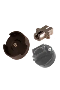
- On all sources, the output connector may be a significant limiting factor. Connector tolerance variations can result in unrepeatable and drift prone performance, which is particularly irritating when trying to measure the performance of, say another connector. Kingfisher sources have an interchangeable interface, to allow the user to change connector styles as their requirements change.
- Various claims are made about the virtue of pigtailed versus receptacle (or lens-coupled) sources. Lens coupled receptacle sources are cheaper to make. Pigtailed sources tend to have better power stability, and better repeatability between patch leads. Claims are made that a lens coupled source is more robust. However, if the receptacle device is damaged, the source has to be thrown away. If the connector interface for a pigtailed source is damaged, the interface can be repaired.
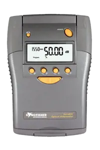
Source power level
Source nominal power levels vary quite widely. The actual power level is not often very important, since a reference is taken before starting work. It is the stability that is critical. When determining approximately how much power is required, the following factors should be considered:
- The expected link loss over which measurements are to be performed.
- Meter sensitivity. Don’t just use the minimum sensitivity value. Look at the specifications carefully to see over what power and temperature range it will be accurate. Many meters require a "zero offset" to be performed to meet low level accuracy specifications. You may want to avoid this problem by keeping the input power level above this range. A better meter could reduce your source costs.
- We have found that low level stray sunlight can leak into fibers and upset low level measurements. A 2 km drum of acrylate coated single mode, left in sunlight with the input end blocked off, can emit up to -40 dBm of stray light. This is a very severe case, so a good rule of thumb for field use, would be to generally avoid measurements below say -50 dBm.
- If your transmission systems use avalanche detectors, it might be a good idea to use a relatively low power laser source. This will avoid accidentally blowing up the receiver if a source is accidentally connected directly into a receiver.
In To achieve repeatable and worst-case attenuation results across the industry, multimode sources should now comply with USA and European standards which define the source center wavelength tolerance, spectral width and Coupled Power Ratio. The standards require loss measurements to be performed using the bi-directional method at two wavelengths, using a standards compliant LED source.
Other issues
Battery systems: Battery life is obviously a major convenience issue. Some Kingfisher sources have a battery life of up to 190 hours. Also important will be an auto-turn off feature, and low battery indicator. Where possible, alkaline batteries are now preferable to re-chargeable types, due to greater convenience, higher capacity, and longer charged shelf life. Should re-chargeable batteries be required, NiMH cells are preferable to NiCad cells since they give longer run times and avoid the problem of disposing of toxic cadmium waste.
Connector: An interchangeable connector is obviously highly desirable, allowing the user to change connector styles. An interchangeable connector also allows better end face cleaning during use.
Ease of use: how long will it take to train operators? Kingfisher sources with similar general features and controls are available over the full spectrum of price and performance. One method of operating all sources, could save a large organization plenty on training costs.
Sources with multiple wavelengths from one connector provide greater productivity when performing multi wavelength attenuation measurements. The following alternative ideas may also improve productivity:
- Some sort of "Autotest" type feature where the source and meter communicate and measure each wavelength alternately. This requires both instruments to have compatible protocols. This greatly improves productivity, reduces skill levels, and improves measurement confidence.
- Note that a major improvement in productivity is possible by using a source with no warmup time. With many sources, dual wavelength verification is very slow because when the wavelength is changed, the source must be left to warm up again. In practice this often results in dual wavelength tests being performed so that the cable is tested at one wavelength, and then re-tested at the other. This takes twice as long!
Safety
The two main regulations governing the safety of sources are the international standard IEC 60825 2011, and the USA regulation 21CFR1040.10. As applied to fibre optics, both standards generally draw a distinction between safety levels above or below 1 mW or 0 dBm. Power levels above this may attract onerous complications in relation to work practices, interlocks, and safety issues, and are therefore to be avoided where possible.
More information