Published in Cable Installation & maintenance Magazine, October 1, 2015
By Bruce Robertson, Kingfisher International
There is much lively debate about what useful distance range to expect when using a visual fault locator (VFL) for testing single mode fiber installations. In this article I will provide my perspective and with it, a methodical analysis.
These days 650-nm high-power VFLs are inexpensive and readily available, so legislation related to laser eye safety is the primary limit on power levels. We assume the widely accepted IEC 60825-2:2021 Safety of Laser Products Part 2: Safety of Optical Fibre Communications Systems (OFCS).
Using different safety standards does not yield very different VFL performance results, as we will find out. However, failing to comply with local occupational health and safety standards exposes organizations to malpractice and bad corporate image-quite apart from possible eye damage, which could be to a child if that child picks up an unsafe VFL that was accidentally left behind on a work site. With broader fiber deployment, it is no longer safe to assume that a VFL will always be used in a restricted work environment.
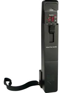
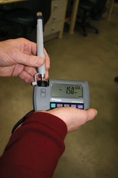
Shown here is a total emission safety test on a VFL pen using a power meter with a large-diameter optical detector. This VFL has a short fiber stub; its total emission is -1.5 dBm, but it couples approximately 3 dB less into a fiber. This is a Class 1 unit; the Class 1 limit is +3 dBm.
Multiple power levels/limits are available.
- The Class 1 limit (+3 dBm/2 mW) is intrinsically safe in all circumstances and is the only class that never requires special site precautions or user training.
- The Class 2M limit (+10 dBm/10 mW) is the highest legally allowed, requires special site signage as well as special operator safety training, and achieves about 1 kilometre more useful range than Class 1. That extra kilometre would have to be very valuable to make the effort and risk worthwhile.
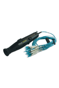
Laser safety is determined by the maximum possible VFL emission, with no coupled fiber. With pen-style VFLs, this is a specific safety issue because of the very short fiber stub, or lack of a fiber stub at all, in these units. The uncoupled emission is often about 6 dB higher than the fiber-coupled emission quoted on the specification.
Because of this issue with uncoupled VFL eye safety, a well-designed instrument-style VFL with a length of internal fiber after the laser, can go about 6 dB (or 1 km) farther than a pen-style VFL that lacks a fiber stub, for the same eye-safety rating.
In the world of VFL use, it’s the worksite operator, not the VFL manufacturer, who is responsible for laser safety. Again, anything other than a Class 1 VFL requires specific site signage and staff training. At Kingfisher International, our research shows a very modest performance improvement in exchange for all this effort. It is our position that a VFL that meets Class 1 specifications without a coupled fiber is the clear default option.
How to determine VFL performance
The performance, or range, of a VFL is determined by the VFL coupled output power (as described in the previous discussion about eye safety), the fiber attenuation, eye sensitivity, and other factors. We’ll look at each of these.
Fiber attenuation
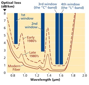
This is always going to be an uncertain factor. The chart in this article, from fiber-optics.info, shows a spread of values. Based on the graph, the very likely values in the 650-nm window (which is just off the graph to the left) would be 5 to 7 dB/km. Note that loss for typical fiber is not usually specified for operation at this wavelength.
This chart shows four wavelength regions of optical fiber. The dashed, dotted, and solid lines correspond to optical fiber manufactured at different times (early 1980s, late 1980s, and more recent).
Additionally, we at Kingfisher measured a 10-kilometer drum of fiber made in the year 2000 and got a 6.3 dB/km measurement. So, we will use 6 dB/km as our baseline. Previous tests produced quite similar results. Note this is many times the loss at, for example, 1310 nm, so this light cannot go very far.
One other important point: High-power VFLs are available only at 650 nm, not 635 nm. Any discussion of so-called “long-range VFL” must usefully be about 650 nm. The highest-powered 635-nm VFLs now available are only about -2 dBm. Therefore, what follows discusses 650 nm only.
Eye sensitivity
This seemed quite consistent among a group of people. The most significant variations relate to ambient light, plastic pigments in cables, what people are trying to do, and exactly how they do it.
In strong ambient sunlight, light often cannot be seen leaking through the side of the fiber bend at all, so using a VFL for fault-finding in daylight may not produce any useful result. We conducted our tests in a typical office environment with fluorescent lighting. We either used just this fluorescent lighting or cupped our hands over the fiber to provide reasonable shade.
This procedure raises some interesting points. For example, trying to conduct fault finding on outside plant cabling would benefit from having a hut over the expected problem area to provide shade. If trying to find a fault indoors, it is helpful to turn down the lighting. The eye is better able to pick up a blinking light, so all our tests used a flashing VFL.
The worst “fluoro lit bend sensitivity” was on 3-mm yellow patch lead, at -16 dBm. The best sensitivity was on 900-μ (uncoloured) fiber, at -20 dBm with cupped hands. Shifting between 3-mm yellow patch lead and 900-μ fiber only caused a 4-dB (<1 km range) variation in our bend-sensitivity tests. However, some other patch-lead pigments can absorb all the red light. Shifting from “fluoro” to “cupped hands” ambient light caused about 4 to 7 dB of variation. Certainly, there is some “operator error” here, and that’s only to be expected because an exact bend radius is rarely repeated. We bent hard!
This is a practical way to check continuity. We used two methods: 1) naked eye, and 2) a microscope with no visible wavelength filter. This raises an important issue: A microscope with no visible filter is highly dangerous for any VFL above Class 2 (5 mW). So, we would not recommend users to use such a scope, but we did this for the sake of completeness. For safety, we’d recommend that scopes be fitted with a red safety filter so that users’ eyes are protected from any VFL.
The difference between using the naked eye and using a microscope was approximately 7 dB, which translates to roughly 1 km of range. With the naked eye, the sensitivity was 57 dBm. Although we did not test it, it is easy to deduce that a “blob” of light from a break will be theoretically visible at about this level, minus 4 to 7 dB of plastic absorption. However, this is an extremely weak level, which would be too hard to see in practice if users are searching around a wiring closet, etc. So, we put a vague number of about -40 dBm on this one, because it may be hard to “shade” the cable run.
Other factors
Several other variables should be considered, such as:
- The exact attenuation of fiber under test.
- Ambient light condition.
- User actions.
- Test type.
- Cable pigments absorbing light.
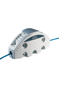
These are all essentially unknowns, and all they are ever going to do is degrade performance. In practice this means that trying to use a VFL toward the limit of its theoretical range discussed here may be an unrewarding experience. Given that fault finding is usually not an easy task, this is perhaps not altogether unexpected. It does, however, mean that you’d want some alternative fault-finding tools available if needed, such as a clip-on fiber identifier or an OTDR.
Once you understand the implications of 6-dB/km attenuation, a lot of often-confusing side issues can be safely ignored. The resulting best-case performance is summarized here. Actual performance may be a lot worse in many cases, but it’s highly unlikely to be much better.
Maximum performance of eye-safe Class 1 (max +3 dBm) VFL
- Up to 4-5 km for continuity testing using a sharp bend, fluoro light and shading with the hand, with an instrument-style unit going the extra distance.
- Up to 6-7 km for break location in a patch lead or closure, fluoro lighting and shading of the cable run, with an instrument-style unit going the extra distance.
- Up to 9-10 km for continuity testing looking at a connector tip with the eye, fluoro light and shading with the hand, with an instrument-style unit going the extra distance.
Maximum performance of unsafe (and illegal) VFL
- Add 1.7 km to the Class 2 range for a 50 mW/19.9 dBm VFL (the highest power we could find).
Conclusion
Some VFL manufacturers claim 20 Km, 30 Km, and 50-km range. However, the farthest a 50-mW VFL can go is approximately 13 km when looking at a connector tip. Our conclusion (and it is quite obvious to us) is that there is really not very much practical performance difference between a safe and unsafe VFL. Furthermore, for distances above a few km, you’d do best to switch to some other technology like a fiber identifier, with a range close to 200 km at 1550 nm.
Bruce Robertson is founder & director of Kingfisher International (www.kingfisherfiber.com). He developed & produced the first commercial solid state Visual Fault Locators in 1992.