Introduction
The issue of optical connector performance is a source of great confusion to many of our customers - you are not alone! Therefore, we present here a technical analysis of common styles of connectors.
A bit of history...
Optical connectors were very hard to bring into commercial production, due to the requirement of very tight mechanical tolerances. So, they have a very long history of improvement and cost reduction. The author remembers when making patch leads was a job for skilled engineers, and they cost about US$300 each! There were only two suppliers worldwide who could make suitably fine-grained ceramic ferrules. The current frontier is how to reduce the level of inspection and skill, and make them truly mass-produced. One of the other problems has been geometry tolerances of the glass fiber, which in the early days made connectors hard to assemble, and performance very uncertain.
So with the improvements in fiber, ceramic materials, overall connector design, and general manufacturing expertise, connectors have come a long way. The performance level has also been improving, and single mode loss figures of the order of 0.1 dB are now becoming realistic in real use.
A variety of commercial termination kits are readily available, for varying levels of productivity, skill etc. When buying a termination kit, first look at the required user skill level and productivity requirement.
Newer connector developments include a smaller 1.25 mm ferrule (LC, MU, LX-5 connectors). New duplex connector designs include the MR-RJ and Volition connectors, both of which have an unusual design intended for low cost and low performance. However, in practice the installed cost is comparable with ceramic ferrule connectors, which have become the de facto standard for all single mode, 50/125 and 62.5/125 um glass fiber.
Essential elements
The essential elements found in most types of connectors are:
- A ferrule, which is used to align the core inside the connector.
- An alignment sleeve, used to mate the 2 ferrules together. This is loosely held inside the through - connector.
- An anti-rotation device, to prevent rotation of the ferrules, and thus end face damage. Also critical for APC connectors.
- An end-pressure control device (spring) to control the end pressure on the ferrules. This is critical to control return loss.
- A strain-relief system to transfer tension from the connector to the strength member and prevent loss of light due to sharp bending of the connected fiber.
- Connectors are always male devices. There is no female device, but a through connector, which contains an alignment sleeve to align the ferrules of two mated connectors.
- A device receptacle is a special form of through connector which mates a connector to a transmitter or receiver device. It is not normally possible to use emitters in device receptacles with APC polish connectors. It is sometimes possible to use detectors in receptacles with APC polish connectors. A few device receptacles have been designed specifically for APC connectors.
Fibers
Fiber tolerances affect connector performance. Variations in mode field diameter, numerical aperture, glass diameter and core concentricity can introduce loss effects that cannot be controlled by the connector manufacturer. Some of these effects depend on the direction from which they are measured. Diameter and core concentricity variations of around 1 micron each are now common, and suppliers are working on bringing this down to 0.5 micron. Connector performance is often observed to be worse than the manufacturer's specifications due to these imperfections.
Optical and mechanical variations can have a major effect on connector performance, which is not really specified by the connectors. With single mode fiber, the dominant effect is typically mechanical tolerances of the core concentricity and glass diameter. whereas with multimode fiber, it is changes in the fiber numerical aperture which usually dominate.
Ferrule tolerance
Single mode connector types have a connector ferrule tolerance which ensures alignment of the glass cladding to the centre axis of the ferrule to within 0.5 - 1 micron. To achieve this, the connector hole diameter is carefully matched to the actual glass diameter ( e.g. hole size 124, 125, 126 micron ). Alternatively, a larger hole with some form of active alignment procedure is used. Single mode connectors tend to be expensive to manufacture, and time consuming to assemble.
Multimode connectors do not require as tight a tolerance as single mode so typically have ferrules with a 127~128 micron hole, so they are relatively easy to make and assemble. In practice during single mode ferrule manufacture, ferrules that fail the required single mode tolerances are allocated as multimode.
There are two types of ceramic used in connector ferrules. Zirconium is extremely hard and cannot typically be polished. It is therefore pre-shaped during manufacture and is ideally suited to field polishing techniques. Alumina is much softer and is easily shaped by polishing. It is therefore better suited to use with mechanized polishing systems where shape can be carefully controlled. The quality of connector achieved by either material is therefore strongly affected by the polishing technique. Both can yield good connectors. Alumina has the advantage that re-work is possible.
Some multimode ferrules are made of plastic or stainless steel, which can provide adequate tolerances for multimode application. However, neither of these are suitable for heavily used measuring leads, due to increased wear and generally worse tolerances.
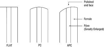
The way a ferrule is polished is critical to connector return loss performance. A "flat polish" connector will cause around -14.7 dB return loss unmated, and up to -11.7 dB mated. ( e.g. two reflections ). A "PC" or "physical contact" connector will cause around -14.7 dB return loss unmated, and between -30 and -60 dB mated, or around -20 dB for multimode fiber. The mated performance is very dependent on the exact polishing procedure (and operator experience), and very sensitive to subsequent dirt and wear.
Therefore, the so-called "super-PC" or "ultra-PC" polish connectors need constant measurement to verify their achieved performance. Also, their poor unmated performance limits their effectiveness in many applications. A better way is to use "APC" or "angled physical contact" polish connectors, which offer better than 60 dB return loss in all circumstances (unless the tip is dirty).
In single mode applications, a clear distinction must be made between flat polish, PC polish and APC polish connector ferrules. This distinction is not based on connector style (FC, SC, LC etc.) but is determined by the nature of the polish on the connector tip.
Color coding
The connector and / or strain relief sleeve or boot is usually color coded to provide indication of the end face type and or the fiber type There are additional typical colors often used to identify particular patch lead types. For example:
SMF APC: Green connector, Patch leads are usually yellow
SMF PC: Blue connector, Patch leads are usually yellow
MMF: Beige connector. OM3 / OM4 patch leads are usually mid-blue.
PC / APC intermateability
PC polish and flat polish connectors can be intermateable with reduced return loss performance. APC polish connectors are not intermateable with any other type, and furthermore there are different and incompatible APC types which are only partially compatible. Careful inspection of an APC connector ferrule will reveal a slightly angled tip. Some APC connectors have a very small protruding section in the centre of the tip.
Expanded beam connectors
A small number of expanded beam connectors are used worldwide. These use lenses to expand the light beam coming out of one ferrule, and then focus it back into the other ferrule. This is more expensive, but has the advantage of making a connector less sensitive to mechanical mis-alignment and dirt. These therefore tend to be used in military, industrial, and other dirt prone environments.
Alignment sleeve characteristics
The alignment sleeve is located in the through connector and is used to align the ends of 2 ferrules so that the cores of the 2 fibers are aligned. Single mode alignment sleeves are generally made from beryllium copper or ceramic. Whereas under ideal conditions ceramic provides lower loss performance, the beryllium copper sleeves tend to be more forgiving of tolerance variations when mating connectors from different suppliers. However metal alignment sleeves can bend, and then cause poor performance. This is a particular issue in test and measurement applications.
Anti-rotation device
An anti-rotation arrangement is generally used to prevent touching glass cores from rotating and splintering.
On single mode connectors, the anti-rotation device is sometimes also used as part of a post assembly core alignment procedure.
On APC polish connectors the performance of the anti-rotation device is very critical, and for this reason APC connectors may have special through connectors, where the tolerances of the anti-rotation features are matched to the connectors so that very precise rotational alignment is achieved.
End pressure control
It is important to control the end pressure on the mating ferrules. Wrong pressure may damage the fibers or make attenuation or return loss performance unreliable. The end pressure control should also prevent disconnection if the attached jumper lead is pulled. Such disconnection will not only disrupt data but may cause the glass to smash when the jumper lead is let go. Because of this damage problem, most connectors used in high value telecom applications, are designed with a "non-disconnect" feature, which makes them more expensive. This basically means providing the connector with a "floating", spring loaded ferrule. The traditional FC connector has always incorporated this feature, however low-cost versions are available that do not.
Strain relief
Strain relief arrangements are critical to system reliability. In addition to anchoring the strain relief (Kevlar), the rubber boot should provide bend relief to the exiting patch lead so that it is bent gently. Problems can occur when the patch lead exiting the connector is bent sharply, causing high loss. This situation is common in patch frames, where a long length of patch lead may be hanging off a horizontal connector.
Performance specification
The loss performance of connectors varies each time a pair is mated, and also between different mating pairs. The specifications quoted are generally the mean value, which is often not achieved. It is much more useful to use both a mean and standard deviation approach to deal with loss values. Also, the specification may assume "ideal fibers", whereas in practical applications this is not achieved. So, some de-rating of specified performance is appropriate for practical test pass / fail criteria.
The return loss performance of PC connectors usually is a function of polishing procedure, not connector design. Also, return loss of PC connectors is uncertain and subject to sudden deterioration due to slight deterioration of the end surface.
Most connectors have a lifetime specified as 500 - 1,000 insertions under ideal conditions. In field conditions this may not be achieved due to dirt, mating with damaged connectors, rough cleaning, or rough handling. This also implies that heavily used connectors (e.g. for testing) require regular replacement.
There is a current move towards 'Small Form Factor' connectors. These are like the older styles, however the ferrule has been shrunk from 2.5 mm to 1.25 mm, so the connector is much smaller. Because of fierce industry pressure, the standards bodies have so far backed off from 'recommending' any particular design. The MU and LC are so far the most popular since they perform well for all applications. Most of the other types do not work well with single mode applications.
High power handling capability
Systems incorporating WDM technologies may have power levels up to +30 dBm. This is beyond the capability of standard connectors, which can become unreliable at levels above about +18 dBm. At this power level, the power density in a single mode core is so high that the slightest imperfection or dirt causes enough heating to crack the glass. At this point a situation called "fiber fuse" occurs, and the damage can start to propagate back down the core. For very high-power levels, either fusion splices are employed, or expanded beam connectors are used to reduce the power density at the joint. To improve safety, The LX5, F3000 and E2000 connector styles incorporate a flap which attenuates the beam when a connector is not inserted in a mating through connector.
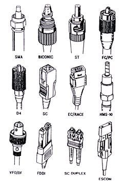
Here is a summary of various connector styles, with some of their appealing and irritating characteristics:
All
| Name |
Application |
Maturity |
Bad Points |
Good points |
| ST |
All |
Common |
Poor disconnect protection results in smashed ends. Some incompatibility. |
Cheap.
Versatile. |
| ST2 |
All |
Old |
Never widely used, SC proved more popular for multimode, FC for single mode. |
Overcomes problem of ST damage. |
| SC |
All |
Common |
Not very robust. |
Conforms to a standard.
High density possible.
Fast push-pull action.
All performance levels.
Can be duplex. |
| FC |
All |
Common |
Compatibility problems between brands.
Threaded retainer.
Panel mount holes very fiddly. |
Common.
Rotate ferrule to tune loss.
All performance levels. |
| LSA (DIN 47256) |
All |
Old |
End pressure control poor on some designs.
Expensive ferrule size.
Compatibility problems.
Threaded retainer. |
Proven reliability.
Compact. |
| FDDI |
Multimode |
Obsolete |
Too large.
Hard to assemble (poor yield).
Strain relief awkward. |
Old duplex connector.
Mates direct with active device receptacle. |
| D4 |
All |
Obsolete |
Weak ferrule.
Poor anti-rotation. |
None! |
| Biconic |
Multimode |
Obsolete |
Different concept.
Bulky.
No anti-rotation feature. |
Did not prove popular. |
| E2000 |
All |
Popular in Europe |
Safety shutter may be transparent to infra red light. |
safety shutter.
High density possible.
Fast push-pull action.
Can be duplex. |
| SMA |
Multi-mode |
Obsolete |
Terrible insertion loss.
No anti-rotation feature.
Threaded retainer.
2 incompatible styles. |
Inherently insensitive to vibration, since connector ends don't touch.
The original connector that worked! |
| LC |
All |
Common |
Fiddly and not robust. |
Small Form Factor Connector, well engineered.
All types conform to a standard
Can be duplex |
| MU |
All |
Mature |
Fiddly and not robust. |
Small Form Factor Connector, well engineered.
All types conform to a standard
Can be duplex |
| LX-5 |
All |
New in Europe |
Fiddly and not robust. European version of LC |
Small Form Factor Connector, well engineered.
All types conform to a standard
Can be duplex |
| MT-RJ |
Multi-mode |
New |
Single mode performance very poor.
Male / female compatibility issues
Hard to clean
Very non-standard overall |
Small Form Factor Connector,
Inherently duplex
No ferrule |
My connector is out of specification - what do I do?
- Use a good microscope to inspect the ends. You need a good microscope with at least x 200 magnification and decent optics. The cheap ones with x 100 are basically useless. If possible, shine white light (a good torch will do) up the core while using the microscope, which will reveal internal fractures. Be aware of optical safety issues when using magnifiers or microscopes.
- Before mating, clean both connector tips with a cleaning cloth or other approved materials. There are some very good "Microfiber" lens cloths (available from spectacle shops), that perform well.
- If it is a connector with screw assembly (FC, D4, SMA, LSA), the retaining thread may not have been tightened properly. With FC connectors, check also that the anti-rotation feature is properly engaged.
- The connector may not be out of specifications, your understanding of what it should achieve may be wrong. Remember that specifications quoted are typical, and so of course will not be achieved all the time.
- In multimode systems, you must perform measurements using a defined modal distribution, otherwise results may appear out of specification. Since the final system may not have a defined modal distribution, in-service measurements may appear out of specification anyway.
- You may have incompatible fibers. If you put a single mode in a multimode system, you will get a loss of more than 10 dB. If you put a 50-micron patch lead into a system with 62.5 micron fiber, you will get a loss of around 3 dB.
- If return loss is the problem on a PC polish connector: Clean the connector parts very carefully, any dirt will affect performance. Check if the connectors were ordered as PC polish, if not, they may not be. Are you measuring backscatter from a long link by mistake? A PC polish connector is only low reflection in the connected condition, otherwise it reflects like any other at -14.7 dB.
- If return loss is the problem on an APC polish connector: Clean the connector very carefully. Check that the through connector is of a type specifically intended for APC connectors. There may be general compatibility problems between brands with APC polish connectors and through connectors.
- If the glass is not properly secured in the connector, it may move. This is called "pistoning". This movement can generally be observed by eye or microscope, however very small movements may upset PC or APC connectors. The most common cause of pistoning, is old or inadequately mixed epoxy used to assemble the connector ferrule.
- If you are mating different brands of connectors, you could have a compatibility problem. Typically: ferrule outer diameter tolerance, anti-rotation features are incompatible, retaining features are not totally compatible, incompatible polish types.
- If it is a single mode connector, on some designs it is possible to tune the loss by rotating the anti-rotation feature. This may not have been done or performed incorrectly.
- If it is a connector type with a spring loaded (compliant) ferrule (typically but not always FC, LC, SC, ST2, D4, FDDI) the connector may have been assembled incorrectly, and the ferrule jammed in place with glue. This can be tested by pushing the ferrule end with something soft and examine the movement.
- You may have "out of specification" fibers. Particularly in single mode applications, glass mechanical tolerances are very important. A certain % of single mode terminations may end up out of specification due to this effect.
More information