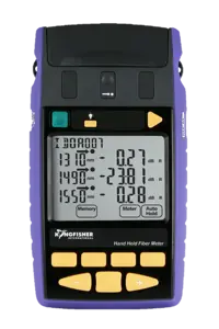
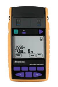
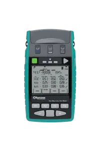
For standards compliant test procedures & equipment, please refer to Standards Center. For more background theory, please read on...
Purpose
Measurement of fiber optic cable loss is an established practice that has been performed for many years. However, over time, the performance of fiber optic equipment has improved, so occasionally it is useful to perform a practical reassessment of the accuracy of these measurements. We have done this here using commercially available Kingfisher International handheld field test equipment, typical “best practice” techniques, and good quality commercially available test cords. The purpose of this study was to examine several practical questions:
- What is the best possible loss test repeatability with one set of instruments?
- What loss test repeatability when using several instruments and test cords?
- What is the effect of using different referencing methods?
- What is the effect of using different types of emitters and detectors?
- What is the impact of test cords?
Summary
This paper summarizes insertion loss testing performed at Kingfisher International in conformance with ISO 14763-3 Information Technology-Implementation and Operation of Customer Premises Cabling-Part 3: Testing of optical fibre cabling, for methods using one and three reference cords. Insertion loss was measured on the following Cabling Under Test (CUT):
- A 10 km length of SMF fitted with LSA/PC-LSA/PC connectors.
- Some patch cords, LSA/PC-LSA/PC and LSA/PC-LSA/APC.
- A 0.549 km length of 62.5/125 MMF fitted with SC/PC-SC/PC connectors.
Using 129 assorted Kingfisher International instruments:
- Typical laser and LED test sources.
- A stabilized edge emitting LED source optimized for precision single mode
testing.
- Random batches of InGaAs, Ge, Si and high-power meters.
- Test cords available from our stock.
Test method
For all testing, commercial quality test cords were used (not special reference grade) For single mode testing, these were Diamond brand patch cords with optically centered connectors. For multimode testing, these were ceramic connectors, the source cord being fitted with a mode filter.
To minimize uncertainty due to performance of test cords and through adaptors, all testing was performed with the same set of test cords and through adaptors, using the same orientation, unless otherwise specified. The through adaptors used had been previously selected to eliminate any with poor performance. For each measurement, the operator recorded the average of 4 insertions.
For referencing we used both the standard 3 cord method and the 1 cord variant method as per ISO/IEC 14763-3 Appendix D. The 1 cord Appendix D variant includes the loss of only one mated connection as opposed to the two mated connections in the standard 1 cord method.
It was also noted that good cleaning technique is extremely important, as even a small amount of contamination would affect repeatability. Prior to making measurements, all optical connectors and connector adaptors were carefully cleaned using a Cletop cleaner, tissues, cotton swabs and small amounts of 100% alcohol as required, then examined under a x200 microscope.
The experimental work was done by someone who, whilst being technically competent, had no knowledge of expected outcomes. Therefore, experimental bias has been minimised.
Test set-up diagrams (as per as per ISO 14763-3)
| Laser Light Source |
KI 3822, APC, 1310/1550 nm |
SM |
5 |
| Laser Light Source |
KI 3820B, PC, 1310 nm |
SM |
1 |
| Laser Light Source |
KI7402, APC 1310/1550 nm |
SM |
1 |
| Laser / LED Light Source |
KI7824B, PC 850/1300nm, 1310/1550 nm |
|
1 |
| Edge Emitting LED Light Source |
KI7419, PC, 1310 / 1550 nm |
SM |
1 |
| LED Light Source, CPR compliant |
KI3812, 850/1300nm |
MM |
3 |
| VCSEL Light Source |
KI3800, +3dBm, 850nm |
MM |
1 |
| Power Meter |
KI3600 H3B |
N/A |
10 |
| Power Meter |
KI3600Si XL |
N/A |
11 |
| Power Meter |
KI3600Ge |
N/A |
33 |
| Power Meter |
KI3600 InGaAs |
N/A |
36 |
| Power Meter |
KI 7601Ge |
N/A |
6 |
| Power Meter |
KI7600Ge |
N/A |
12 |
| Power Meter |
KI7600 InGaAs |
N/A |
10 |
Test results
Uncertainty values are presented using a 95% confidence factor.
Single mode
10 Km of fiber tested with batches of power meters, two laser sources, the same test cords, and one cord reference method.
| Light Sources |
Power Meters |
Average loss @ 1310 nm, dB |
Uncertainty, ±dB |
| KI7824B, PC |
KI3600 InGaAs |
3.87 |
0.08 |
| KI3820B, PC |
|
3.87 |
0.08 |
| KI7824B, PC |
KI3600 Ge |
3.90 |
0.06 |
| KI3820B, PC |
|
3.86 |
0.08 |
10 Km of fiber tested with PC and APC connector laser sources, a batch of power meters, the same test cords and one cord reference method. The lack of variation is not surprising since a PC connector was plugged into the power meter. We note that it’s quite likely that using an APC connector at the power meter might improve these results.
| Light Sources |
Power Meters |
Average loss @ 1310 nm, dB |
Uncertainty @ 1310 nm, ±dB |
Average loss @ 1550 nm, dB |
Uncertainty @ 1550 nm, ±dB |
| KI7402, APC |
KI3600InGaAs |
3.96 |
0.06 |
2.44 |
0.06 |
| KI7824B, PC |
KI3600InGaAs |
3.87 |
0.08 |
2.43 |
0.02 |
10 Km of fiber tested with InGaAs, Ge and H3B power meters, a single laser light source, the same test cords, and one cord reference method. The InGaAs detectors performed better than Ge detectors, as expected, since Ge detectors have an intrinsic non-linearity of around 0.03 dB. The anti-reflection coating of an InGaAs detector is usually optimized at 1550 nm, so the results at 1310 nm are often not quite so good. The results obtained here (Table 4) are in general agreement with these known detector limitations:
| Light Sources |
Power Meters |
Uncertainty @ 1310 nm, ±dB |
Uncertainty @ 1550 nm, ±dB |
| KI7824B, PC |
KI3600n InGaAs |
0.08 |
0.02 |
| KI7824B, PC |
KI3600Ge |
0.06 |
0.08 |
| KI7824B, PC |
KI3600H3B (high power) |
0.06 |
0.10 |
10 Km of fiber tested with a stabilized edge-emitting LED source, two batches of power meters, the same test cords, and one cord reference method. The combination of stabilised edge-emitting LED source and InGaAs detectors gave us the best level of single mode loss testing repeatability.
| Light Sources |
CUT |
Power Meters |
Average loss @ 1310 nm, dB |
Uncertainty @ 1310 nm, ±dB |
Average loss @ 1550 nm, dB |
Uncertainty @ 1550 nm, ±dB |
| KI7402, APC |
10 km SMF |
KI3600 InGaAs |
3.92 |
0.02 |
2.46 |
0.02 |
| 10 km SMF |
KI3600 Ge |
3.98 |
0.04 |
N/A |
N/A |
10 km of fiber tested with the stabilized edge-emitting LED source, two batches of power meters, and the same test cords, both one and three cord reference methods. The repeatability for the 3-cord method is slightly lower, however in practice, this is likely to be swamped the effect of changing test cords, as discussed later on in this paper. This result is possibly limited by intrinsic Ge detector non-linearity.
| Light Sources |
KI3600 Ge Power Meter batch |
Uncertainty, ±dB for one cord referencing @ 1310 nm |
Uncertainty, ±dB for three cord referencing @ 1310 nm |
| KI7419, PC at 1310nm |
1 |
0.04 |
0.12 |
| 2 |
0.04 |
0.06 |
10 km of fiber tested with five pairs of laser sources and power meters, and the same test cords.
| Uncertainty, ±dB for one cord referencing at 1310nm |
Uncertainty, ±dB for three cord referencing at 1310nm |
| 0.08 |
0.06 |
10 km of fiber tested with five pairs of laser sources and power meters, and five sets of test cords. These results clearly demonstrate that when comparing results taken using multiple pieces of equipment and test cords, changing the test cords is the dominant factor affecting repeatability. This is also consistent with the idea that test cord orientation matters.
| Uncertainty, ±dB for one cord referencing at 1310nm |
Uncertainty, ±dB for three cord referencing at 1310nm |
| 0.4 |
0.46 |
Multimode
A. 0.5 Km of fiber tested with a LED source, a batch of power meters, the same test cords, and one and three cord referencing.
| Light Sources |
Power Meter |
Average loss @ 850 nm, dB, 1 cord referencing |
Uncertainty @ 850 nm, ±dB, 1 cord referencing |
Average loss @ 850 nm, ±dB, 3 cord referencing |
Uncertainty @ 850 nm, ±dB, 3 cord referencing |
| KI3812 |
KI3600Si |
1.87 |
0.01 |
1.88 |
0.016 |
Similar testing with a VCSEL light source resulted in highly unstable and
temperature-dependant measurements. Therefore, the VCSEL source was
deemed to be unsuitable for precision loss testing.
B. 0.5 Km of fiber tested with five LED sources, five power meters, one set of test cords, one and three cord referencing.
| Uncertainty, ±dB for one cord referencing at 850 nm |
Uncertainty, ±dB for three cord referencing at 850 nm |
| 0.3 |
0.32 |
0.5 Km of fiber tested with five LED sources, five power meters, five sets of test cords, one and three cord referencing.
| Uncertainty, ±dB for one cord referencing at 850 nm |
Uncertainty, ±dB for three cord referencing at 850 nm |
| 0.42 |
0.38 |
Conclusions:
Single mode fiber:
The best loss testing uncertainty of 0.02 dB (e.g. close to the resolution of the equipment used), was obtained using a KI7419 stabilized edge emitting LED source, a one cord reference method, and an InGaAs power meter (Table 5). This method would be highly suitable for use in manufacturing QA such as commonly encountered by device and patch cord manufacturers. Since our test instruments have a display resolution of 0.01 dB, it’s possible that this result could be improved further. This result was expected, since it eliminates two problems: the effect of optical reflections affecting laser source power, and the effect of optical coherence on detector responsivity.
Laser sources can be sensitive to back reflections. In a low reflection (e.g., APC connector into power meter) test condition, uncertainty of about 0.06 dB was obtained, and in a high reflection (e.g., PC connector into power meter) test condition, uncertainty of about 0.1 dB was obtained. (e.g., Table 4)
We confirmed that for best practice results, it is important to retain the orientation of both test cords and through connectors. If these are randomly oriented, the accuracy will be degraded.
The worst level of repeatability with uncertainty of 0.4 dB resulted from randomly mixing test cords & orientation, through connectors & orientation, and test equipment. (Table 8)
We conclude that the effect of randomly mixing Kingfisher test equipment is usually quite small compared to the effect of changing test cords. With other brands of test equipment, this may not be so.
Surprisingly, we did not find a significant difference in repeatability using the 1-cord and 3-cord techniques. The 3-cord test was only performed using the less repeatable test methods, since these are the situations in which it would be used.
Multimode fiber
The best loss testing uncertainty, with uncertainty of 0.01dB was obtained using one CPR compliant LED source, 549 meters of multimode fiber, and a one cord reference method (Table 9).
However multimode testing is sensitive to launch conditions, and therefore different light sources. Even using CPR compliant sources, we found that changing sources created an uncertainty of about 0.3 dB (Table 10)
The worst level of repeatability with uncertainty of 0.4 dB resulted from random mixing & orientation of test cords, through connectors and test equipment.
Use of a VCSEL laser severely affected repeatability and was also significantly more temperature sensitive. A VCSEL could not be recommended for precision work since the meter is unstable unless the resolution is reduced to 0.1 dB. Any technician using such a source would have a low level of confidence in results, since a good stable reading is rarely obtained.
So, we concluded that an LED should always be used for multimode testing, even though the modal fill may not be a very good match with the transmitter on a real data system.
Single mode and multimode fiber
We found that for both fiber types, “best practice” loss testing uncertainty was of the order of 0.01 dB with a single set of equipment and test cords, and in a more general scenario with random equipment and test cords, was of the order of 0.4 dB. We were quite surprised by this similarity, since the dominant factors appear to be quite different in each case.
The “best practice” single mode test results were obtained using a special edge-emitting LED stabilised test source.


