For standards compliant test procedures & equipment, please refer to Standards Center. For more background theory, please read on...
Introduction
This is the simplest fiber optic cable testing procedure. Patch leads should be of similar type to the DUT. F or multimode measurements, a mandrel wrap forms part of the source reference condition. Communication is required between the two operators.
Method
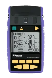
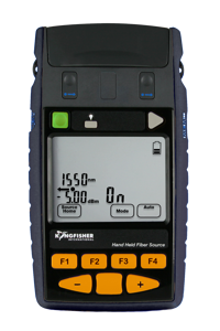
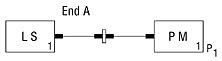
1. Clean the connectors. Connect the source and meter using two patch leads and a through connector (or one patch lead and no through connector for the building cabling method), set the source and meter wavelengths. Allow the source to warm up and stabilise. Measure and record the reference power P1 dBm [For meters which have a relative dB measurement facility, put the meter in relative mode and set the reference]. For dual wavelength work, also reference the other wavelength at this point, after a further warm up period.
Note: it is good practice to occasionally check your patch leads by reversing them (e.g. the other ends go into the through connector), and re-measuring the reference value, which should only deviate within the expected tolerance of your connectors.
2. Leave the patch leads connected to the instruments (or the one patch lead on the source for the building cabling method), since removing them adds to measurement uncertainty.
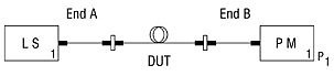
3. Insert the DUT into the measurement set up, using an extra through connector if needed, and record measurement P2 in dBm [if the same reference value was used, the attenuation is displayed directly in dB. Step 5 is not required]
4. Remeasure the source power as in set-up 1, to verify the source drift remain within acceptable limits.
5. Calculate the attenuation (dB) of the link as: Link attenuation in dB = P1 - P2
6. Repeat at the same wavelength for the other fibers (the order of 5 & 6 may depend on source warm up characteristics)
7. For dual wavelength measuring, change the source wavelength, wait for the source to warm up, then go back to step 3.
Disadvantages
- May require operators in two places.
- May require operators to swap instruments if measuring bi-directional losses.
- The time to swap instruments to other end of link can create problems with source stability and battery life.
- It may be impossible to use a single integrated LTS, if that is what you have.
In this situation 'Autotest' type features can result in better measurement confidence, lower skill requirements and twice the productivity for dual wavelength measurements, since both wavelengths are measured in one operation, and the attenuation is displayed directly.
Key