For standards compliant test procedures & equipment, please refer to Standards Center. For more background theory, please read on...
Introduction
This note describes the 3 main fiberoptic attenuation measurement methods, which are:
- Cut Back Method
- Insertion Loss Method
- OTDR Method
Each method has its place and offers varying degrees of accuracy or convenience.
Definition
Insertion Loss (IL) is defined as the total decrease in power between the input and output terminal of the Device Under Test (DUT).
Cut back method
The cut back technique offers the highest measurement accuracy and resolution, however it is time consuming and impractical in most situations, since it requires fibers are cut and cleaved as part of the measurement process. Its usage is typically confined to R&D or quality assurance laboratories.
This method is the reverse procedure of the more common insertion loss technique.
For multimode measurements, a device to control modal distribution may be required. On some (probably old) fibers, some method of performing cladding mode stripping may be required.
- Turn on the instruments, set the wavelength, and leave to warm up. Clean and inspect the patch leads.
- Set up the source reference condition, using cladding mode stripping patch leads and mandrel wrap as appropriate.
- Measure the output power from the DUT = P2 dBm.
- Cut the input fiber from the DUT. Cleave the end and measure the input power to the DUT = P1 dBm. Hence the name ‘cut back’.
- Compute the attenuation in dB of the DUT, eg P1 - P2 dB.
- Many meters have a reference facility, which if used correctly, eliminates the last step and displays the losses directly.
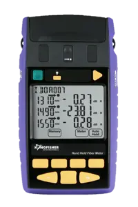
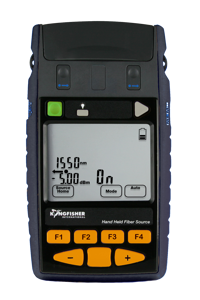
Source 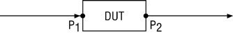 Meter
Meter
Further reading; TIA/EIA 455-78A, Spectral-Attenuation Cutback Methods for Single-Mode Fibers.
Insertion loss method
The insertion loss technique is more practical for field work. However, measurement uncertainty is compromised by connector loss uncertainty. It is commonly used in field situations where acceptable measurement performance is obtained regardless of connector performance.
It is common practice to perform the technique in two directions and average the result. It ia also commonly performed at two wavelengths.
- Turn on the instruments, set the wavelength, and leave to warm up. Clean and inspect the patch leads.
- Set up the source reference condition, using cladding mode stripping patch leads and mandrel wrap as appropriate.
- Measure the source output power P1 dBm.
- Connect the DUT, and measure the output power from the DUT = P2 dBm.
- Compute the loss in dB of the DUT, e.g. P1 - P2 dB.
- Many meters have a reference facility, which if used correctly, eliminates the last step and displays the loss directly.
Source Meter
Optical TDR method (backscatter)
This backscattering method of measuring loss is particularly suitable for measuring and locating point losses along an installed system, such as those caused by a fusion splice. Due to several factors the measured value is less accurate than the other two methods.
An optical time domain reflectometer is essentially an optical radar. It puts out a powerful light pulse, and then measures the reflected signal amplitude over time. The reflected signal is very weak and requires extensive averaging to reduce detection noise. The user has to input some information such as refractive index (the speed of light in glass relative to the speed in a vacuum). From this, it mathematically deduces the power level at each point along the link, and from this, it is possible to determine loss figures, and the location of point losses.
Importantly, to achieve accurate absolute loss certification, loss must be measured from each end, and averaged. For craft level measurements, and to certify point losses, this is a valuable tool.
The source / meter measurement is still required, because it provides unambiguous end to end loss measurements, including the connectors each end, whereas an OTDR has some difficulty in doing this.
An optical TDR has difficulty to accurately measure installed splitter-based systems, such as PON applications, so a source / meter measurement is required. There are two reasons for this: Firstly, because it can only work in one direction where spitters are used. Secondly, the loss created by eg a 16 way splitter is around 15 dB, so only a high performance instrument set on a long pulse length can see beyond the splitter, and in this mode it has very poor spatial resolution. The typical specification for dead zone in this mode is too long to be useful in a short distance network.
Further reading: Optical Time-Domain Reflectometry by Duwayne Anderson and Florian Bell. Tektronix Part Number 001-1134-00