Introduction
This note details some single mode & multimode ORL verification measurements using the Kingfisher KI734xA series Two-Way Testers with ORL. These procedures can be used to verify instrument performance. Following these procedures enables a novice user to gain an appreciation of ORL causes and effects.
Scope
This note covers some basic unidirectional ORL measurements:
- Measure a reference ORL level to verify basic calibration, and perform a user offset.
- Measure a residual reflection level, and perform a user offset.
It does not cover instrument operation otherwise covered in the manual, Autotest ORL operation, connector cleaning or inspection methodologies.
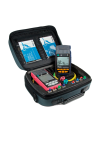
Apparatus required:
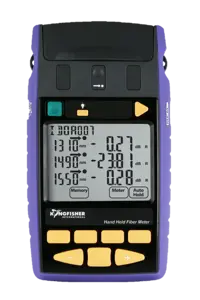
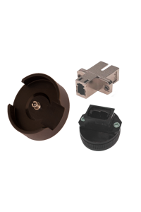
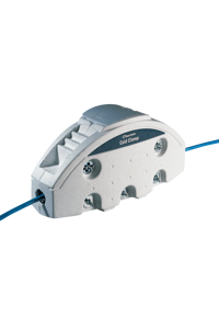
- One KI734x Series single mode or multimode ORL meter, with either of the following additional parts:
- For an APC Connector instrument:
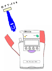
- OPT704, PC terminator. OPT704A, APC terminator, Patch cord, multimode or single mode PC-APC, < 5 meters.
- For a PC Connector instrument:
Preparation
ORL is strongly affected by connector cleanliness and end face quality. A slightly dirty APC connector may back reflect, even if its forward loss is normal.
- Ensure all connectors are clean and end faces in good condition.
- Fit appropriate connector adaptor to left instrument port, which is the ORL measurement port in addition to being the two-way and source port.
Using a microscope, it is not possible to determine the likely ORL performance of a clean and undamaged connector. This is determined by the connector polishing technique.
Precondition the patch cord
Standards specify that to improve measurement accuracy and stability, a mode filter should be used on the patch lead between the ORL meter and DUT.
Single mode
A mode filter on single mode fiber is specified by the standards, however in most situations the effect is small, and it’s often omitted: Two turns of 50 mm diameter are specified.
Multimode
This is a significant factor to achieve consistent results. This is a different diameter to the mandrel wrap specified for loss measurement. Five turns around a mandrel of typical diameter:
| Fibre Size µm |
Mandrel Diameter mm |
| 50 |
18 |
| 62.5 |
20 |
| 100 |
25 |
ORL performance verification
All connections are to the left-hand instrument port. The instrument connector type is fixed PC or APC and is labelled on the instrument close to the left hand connector.
Verification for APC connector instrument
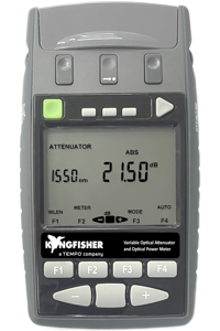
- Turn on the instrument by pressing the green [POWER] button.
- Enter ORL measurement mode by pressing [Return Loss]
- Toggle [-/+] for required wavelength.
- Connect patch cord to instrument. The APC end is plugged in to the instrument, with an un-mated PC connector at the far end.
- The instrument should now read 14.66 ±0.7 dB, in which case the instrument calibration is within specification. This is derived from:
(14.26 dB typical reflection + 2 x typical connector loss @ 0.2 dB) ± (rms (2 x connector loss uncertainty@ 0.5 dB + instrument uncertainty of 0.5 dB)).
If outside this spec, or if compensation is required for connection losses to the DUT, user calibration (UCAL) can be used to apply an offset on the above result. Refer Section 6.
- Plug the PC terminator onto the patch lead end, and observe the instrument reading:
- If single mode, the reading should be below 35 dB, in which case both the patch lead and terminator are working properly.
- If multimode, the reading should be below 20 dB, in which case both the patch lead and terminator are working properly.
Note: This condition can be used to apply the instrument ORL zero function if the same PC patch leads and terminators will be used for measuring. Refer Section 6.
- Remove the patch cord from the instrument and plug in the APC terminator.
- If single mode, the reading should be below 60 dB, in which case both the instrument and terminator are working properly.
- If multimode, the reading should be below 40 dB, in which case both the instrument and terminator are working properly.
Note: This condition can be used to apply an instrument ORL zero function if the same APC terminator will be used for measuring. Refer section 6.
| ORL Performance verification for KI 7340 series APC instrument |
| Parameter |
Specification |
Measured value |
| ORL Unterminated Patch lead |
14.66 ± 0.7
13.96 – 15.36 |
|
| ORL Terminated Patch Lead |
SM < 35 dB
MM < 20 dB |
|
Verification for PC connector instrument
- Turn on the instrument by pressing the green [POWER] button.
- Enter ORL measurement mode by pressing [Return Loss].
- Toggle [-/+] for required wavelength.
- With no patch lead connected to the instrument, observe the reading.
- The instrument should now read 14.26 ±0.5 dB, in which case the instrument calibration is within specification. If outside this spec, user calibration (UCAL) can be used to apply an offset.
- Plug the PC terminator into the instrument and observe the instrument reading:
• If single mode, the reading should be below 35 dB, in which case both the patch lead and terminator are working properly.
• If multimode, the reading should be below 20 dB, in which case both the patch lead and terminator are working properly.
Note: This condition can be used to apply an instrument ORL zero function prior to making a low-level measurement. Refer Section 6.
| ORL performance verification for KI7340 series PC instrument |
| Parameter |
Specification |
Measured value |
| ORL Unterminated instrument connector |
14.26 ± 0.5
13.76 – 14.76 |
|
| ORL Terminated instrument connector |
SM < 35 dB
MM < 20 dB |
|
Advanced operation
To improve accuracy:
- When performing measurements at levels within 10 dB of unwanted residual back reflections, use the ORL Zero function.
- To compensate for unwanted forward attenuation in a measurement set-up, use the UCAL mode.
- Restore default settings for these functions.
Note:Hidden keypad operation requires use of the [SHIFT] button. These function descriptions are shown on the back of the hinged cover.
Setting the Noise Floor / ORL Zero function
To compensate residual reflections prior to making a low-level measurement.
Set up the residual ORL condition, then:
- On the hidden keypad press [SHIFT]
- Press [NF SET]. (dBm/W)
- Press [SET]
UCAL Mode
To compensate for attenuation in measurement jigs etc.
A known optical reference condition should be used to calibrate the instrument and Jig. This could be:
- A new, clean, PC connector end, which will provide -14.26 dB back reflection.
- A gold flashed end providing 0 dB back reflection.
Allow twice the connector loss as error i.e., typically ±2*0.25=0.5 dB
- Set up reference optical condition.
- On the hidden keypad press [SHIFT].
- Press [RL ADJ].
- Press [-/+] to adjust display value.
- Press [SET].
Restore defaults
This re-sets both the ORL zero function and UCAL to default settings:
- On the hidden keypad press [SHIFT]
- Press [DEFAULTS]
Guidelines
Kingfisher ORL meters work on the OCWR principle. Light is injected into the DUT where it travels along its length and is both reflected back to the source and attenuated by its passage. The logarithmic ratio of light received to that transmitted is the ORL. It is a positive number, but within the industry is variously referred to in either positive or negative terms. ORL = -10Log10 (Pr/Pi)
The terms "back reflection" and "return loss" tend to get used indiscriminately, although they are in fact quite distinct,
Back reflection refers to the % of reflected light at a particular event. This is the same as the measured return loss if there is no attenuation between the point and the measuring instrument, and if there is only the one reflective event. The measured return loss is the sum of all of the back reflections in a system, less the attenuation between the reflections and measuring point, which of course is complicated to calculate. Usually, only one or two reflections dominate the measurements.
As a general rule, residual ORL should be at least 10 dB lower than the device under test (DUT), to keep within a 1 dB measurement linearity limit. However, if a zero offset function is performed, the residual level can be up to 10 dB greater than the DUT ORL figure. (e.g., a 20 dB range improvement)
For measuring MM ORL smaller than 20 dB, or SM ORL smaller than 40 dB, an APC instrument connector is recommended.
For lengths greater than a few Km, the ORL will approach a stable figure of about 32 dB. As a result, at 1550 nm, single mode lengths greater than approximately 45 Km do not need to be terminated at the far end.
Mandrel wrap reflection terminations do not work for multimode fiber.
Patch lead connector cleanliness and condition are paramount. Visual inspection with a microscope should be considered prior to low ORL measurements.
The ORL performance of patch leads can be ascertained whilst performing noise floor ORL verification. If one or more patch leads are inserted between the termination and the instrument the noise floor should not change substantially.
A flat fiber end (cleaved or polished) has a single glass-to-air (or air-to-glass) interface with an ORL of about 14.26 dB. A reflective connection (eg two mated connectors with an air gap) has two glass-to-air interfaces, so will have an ORL about 3 dB lower of approximately 12 dB. Multiple reflective connectors will add to this. For example, two of these reflective connections will be about 3 dB worse than 12 dB, e.g. around 9 dB.
Faulty patch leads will give divergent ORL results. Good patch leads will return similar results.
ORL repeatability error is at least twice the loss of the patch lead connector to the DUT.
References
IEC 61300-3-6 Fibre optic interconnecting devices and passive components – Basic T&M procedures – Part 3-6: Examinations and measurements – Return loss
Kingfisher International Application Note A6, Return Loss & Back Reflection.